Work
Six jobs, each shown the same way: what was drawn, then what was built. The project, then the results.
Reverse engineering and production, with EhPro
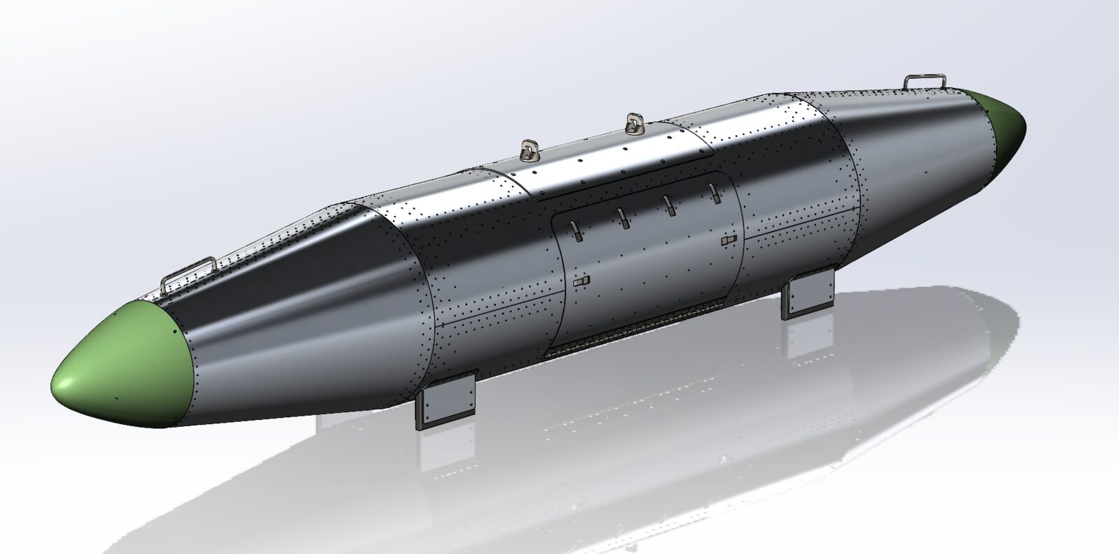
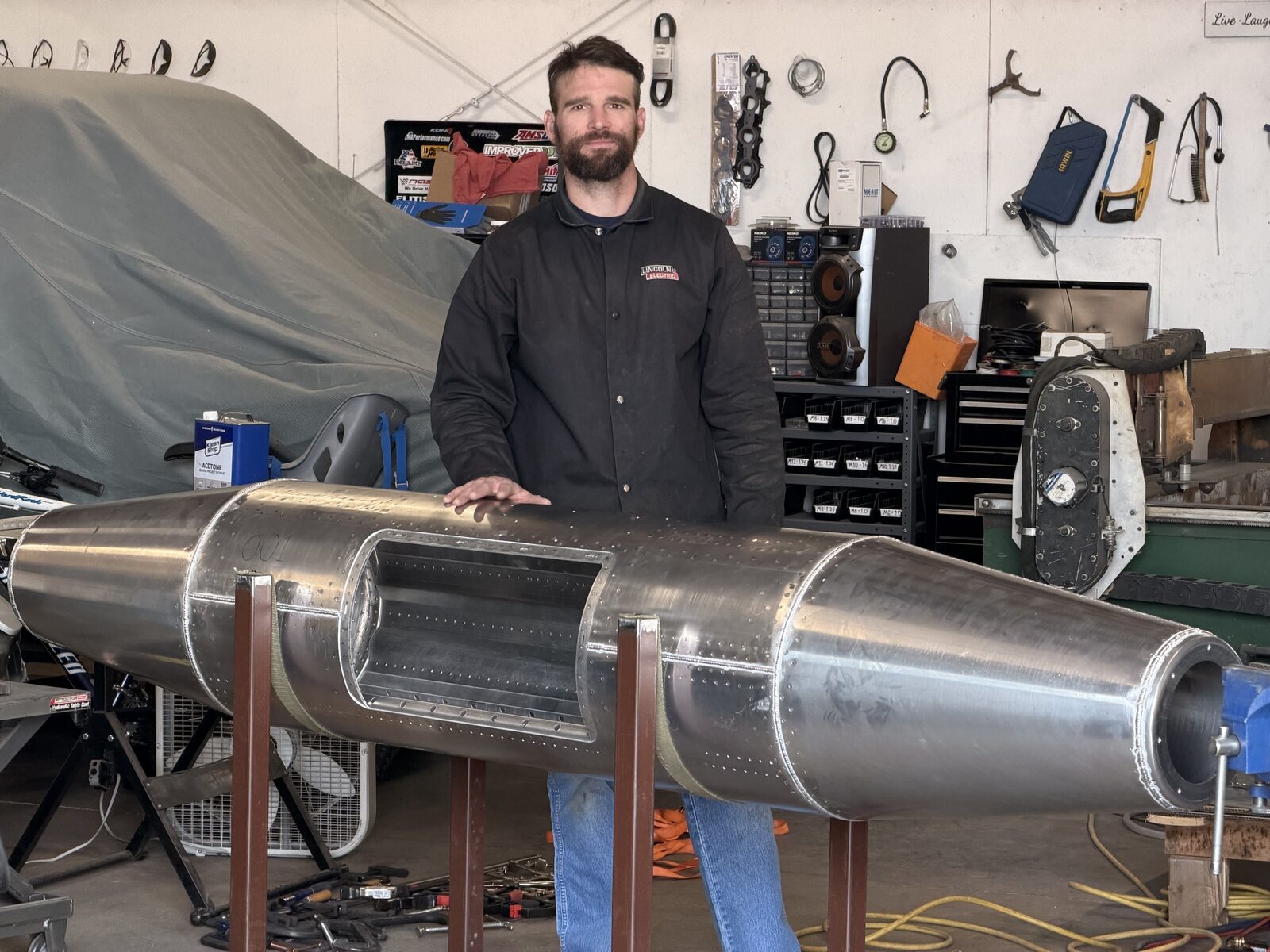
Air Force travel pods
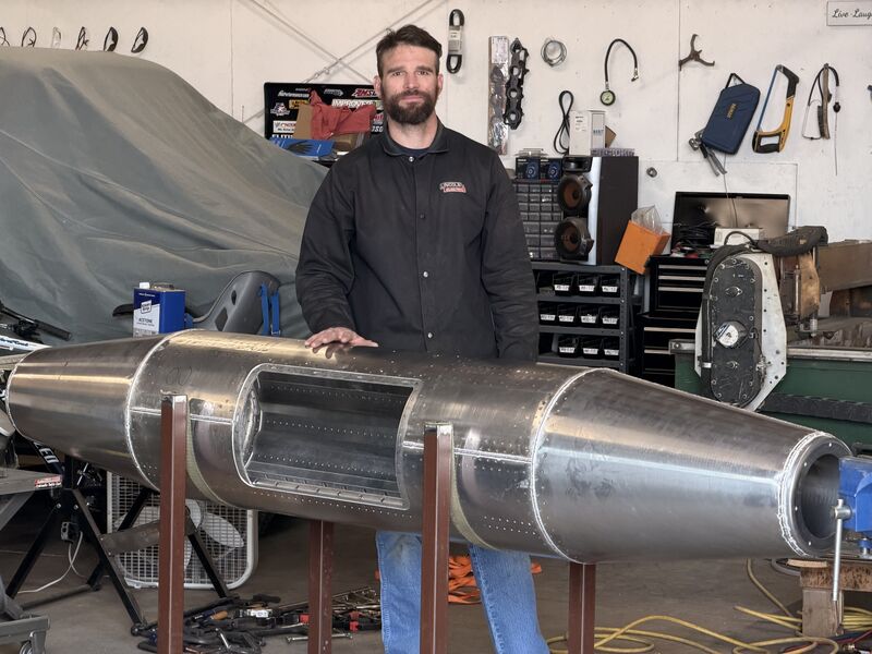
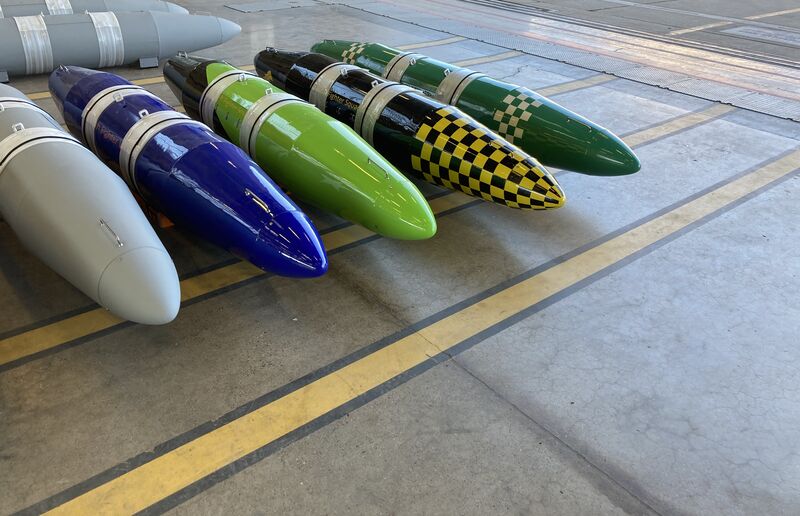
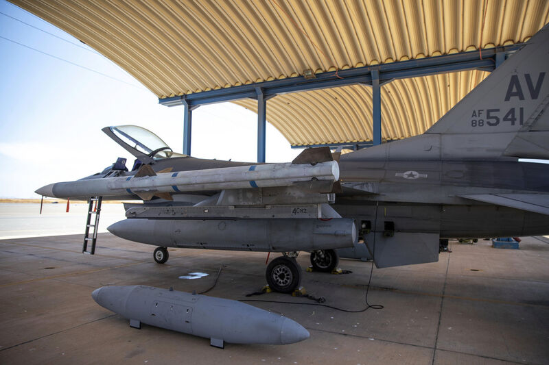
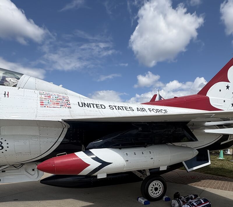
- The projectWhen a fighter jet needs to deploy or go somewhere for training, there is an extensive list of things that need to go with it: toolboxes, equipment, luggage, etc... The maintenance crews pack much of these items into Travel Pods to make sure that it all goes with the jet. EhPro has decades of experience refurbishing used Travel Pods and knows them inside and out. But when an opportunity came along to build brand new ones from scratch, it came with a requirement for CAD models and shop drawings so that the details of the construction could be confirmed and analyzed by the Air Force. At the time EhPro had no in-house CAD capabilities. So they turned to Mechanical Superiority for help, and a harmonious partnership was born.
- The resultsA prototype pod was shipped to Mechanical Superiority in Colorado, and the pod was measured extensively, with minimal disassembly as-required. Combined with remote communication (including some emailed hand drawings back and forth), this process yielded accurate CAD models and assembly, and a full set of construction-ready shop drawings for EhPro. The customer was extremely satisfied with the quality and usability of the shop drawings, and the Air Force got the CAD models they needed to confirm and approve the design so that the customer could massively upgrade their product line. The CAD models also allowed EhPro to upgrade their manufacturing capacity: With the support of Mechanical Superiority's CAD/CAM capability, EhPro decided to acquire a Haas CNC Gantry mill so that the major components of the pods could be made with substantially increased precision. The result has been a radical reduction in the unit production time of the pods, as well as a better-looking and more consistent end product. Mechanical Superiority is now partnered with EhPro and also assists in the construction of the pods (riveting and TIG welding of the main bodies). At risk of understatement: Not many engineering partners bring this much to the table.
- YearOngoing
Remote CAD and rapid prototyping
Bicycle brake adapters
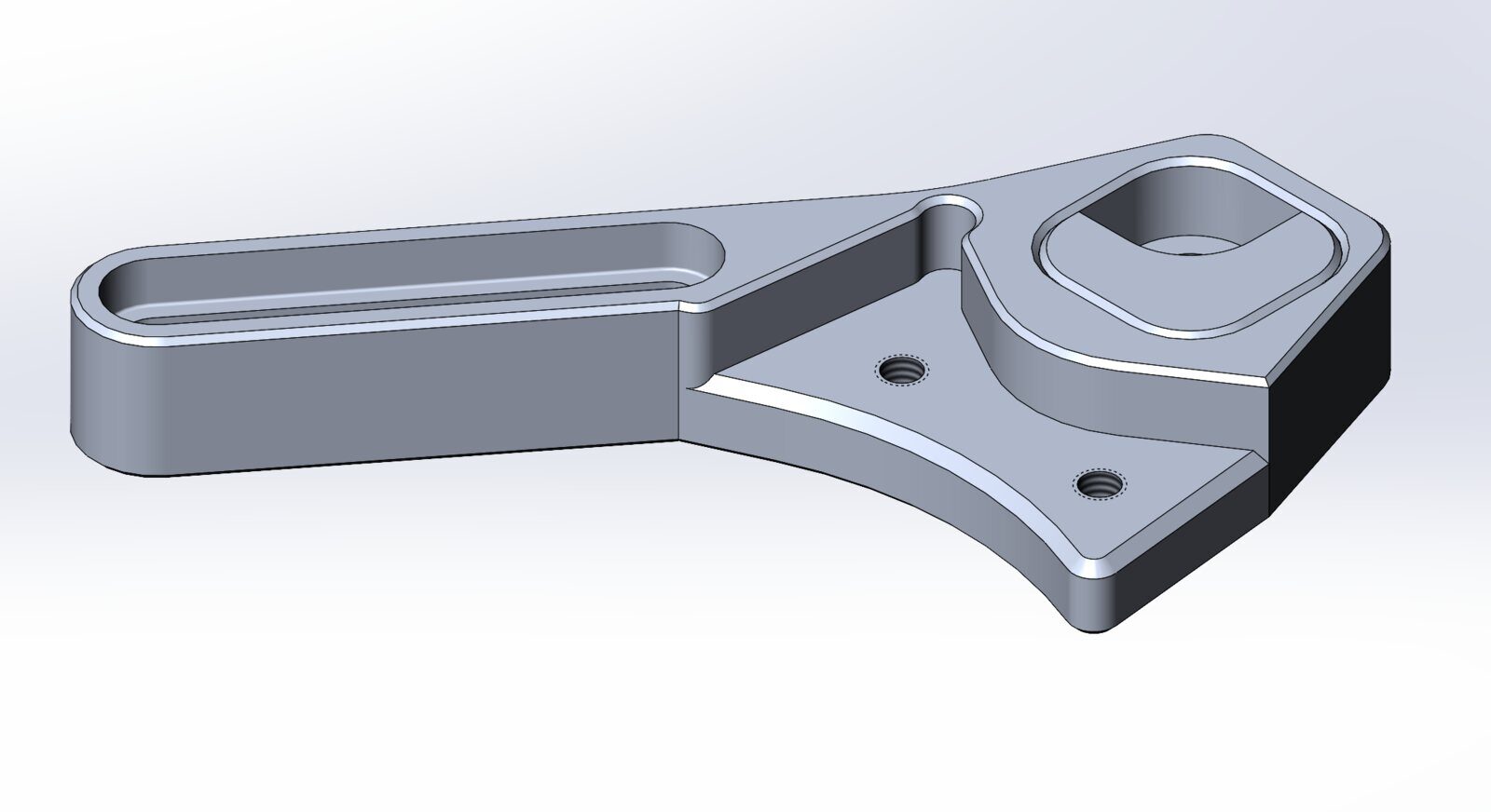
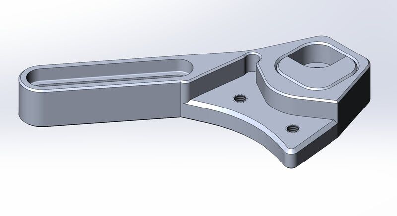
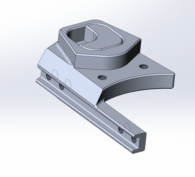
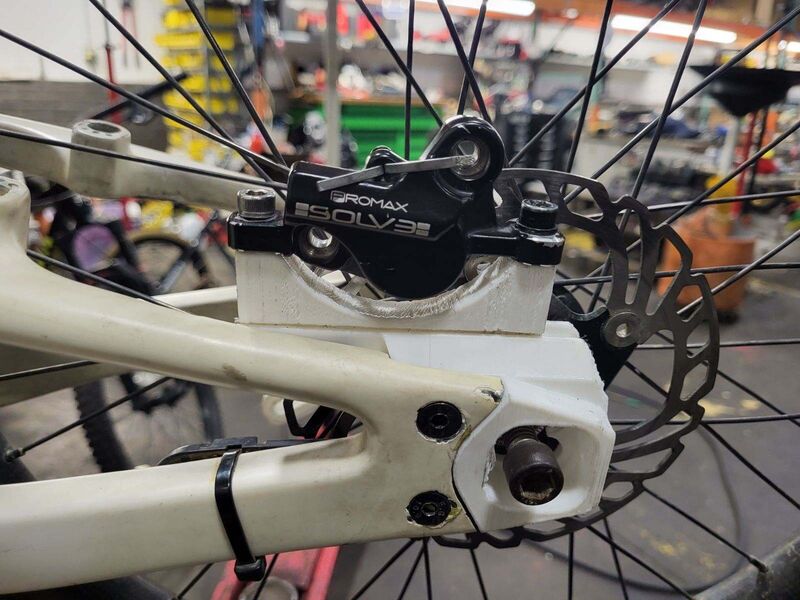
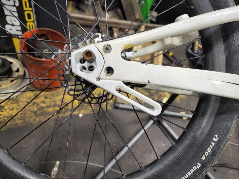
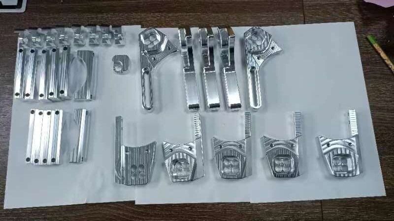
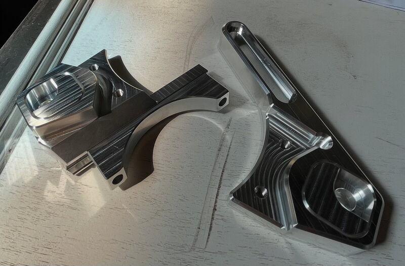
- The projectWhen a customer in Virginia came up with a design for a product he wanted to market, he ended up buying some CAD software and teaching himself how to use it. After a long learning curve, he was able to produce sufficient models, but they were finicky and every change he tried to make resulted in problems that were time-consuming to correct. When the customer contacted me initially, he was looking for someone to machine the parts he already had. But once we started talking, it became clear that what he really wanted was design help.
- The resultsBy taking his models and re-creating them in a way that design changes could be made rapidly by a professional, the iteration process was cut down from days to minutes. This enabled us to work together remotely to rapidly 3D-print plastic models on his end based on the design changes to check fit and finish of the parts. That way we could both be certain that the end product was going to fit and perform flawlessly before cutting metal. With my manufacturing experience I also helped the customer to pair up with a CNC shop to get multiple runs of parts machined and delivered to the satisfied customer. The parts bolted up and fit the first time, and they looked great in 6061-T6!
- Year2024

Aluminum fabrication with an artistic element
Aluminum cloud signs
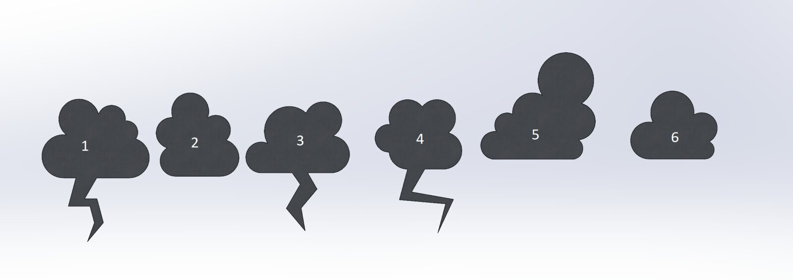
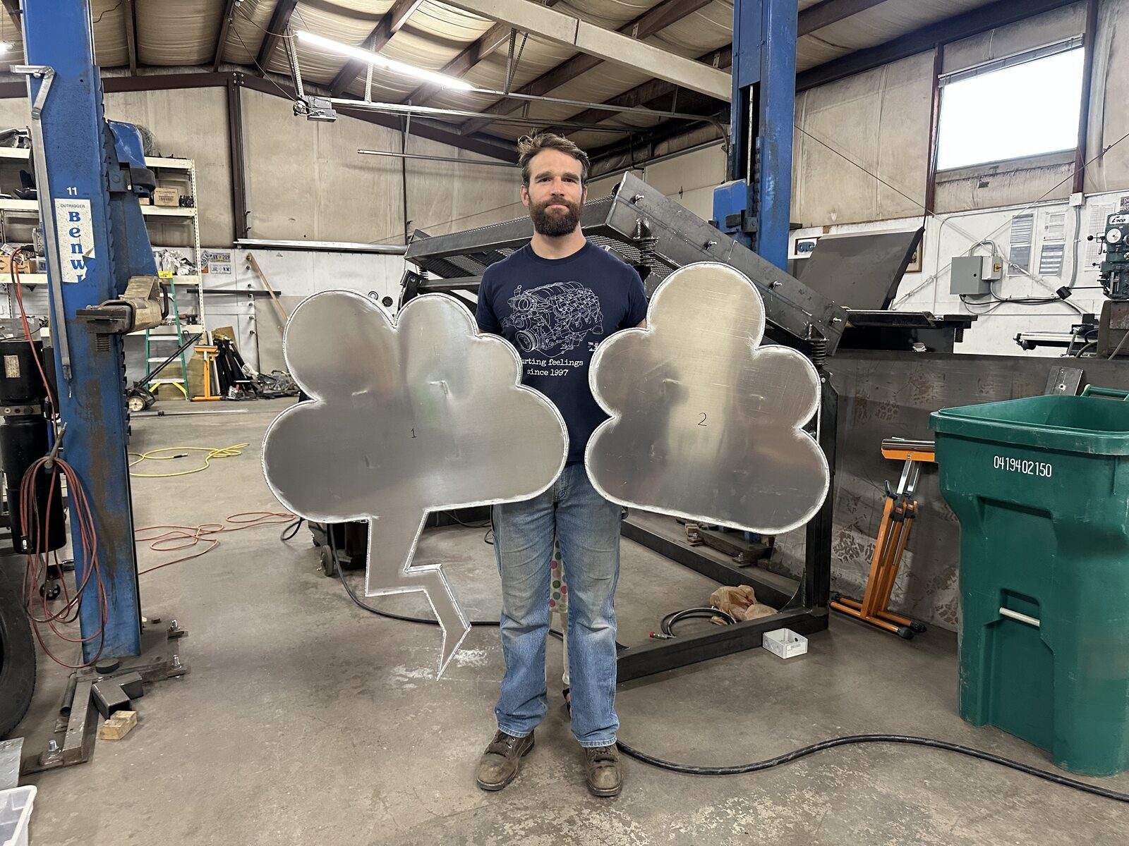
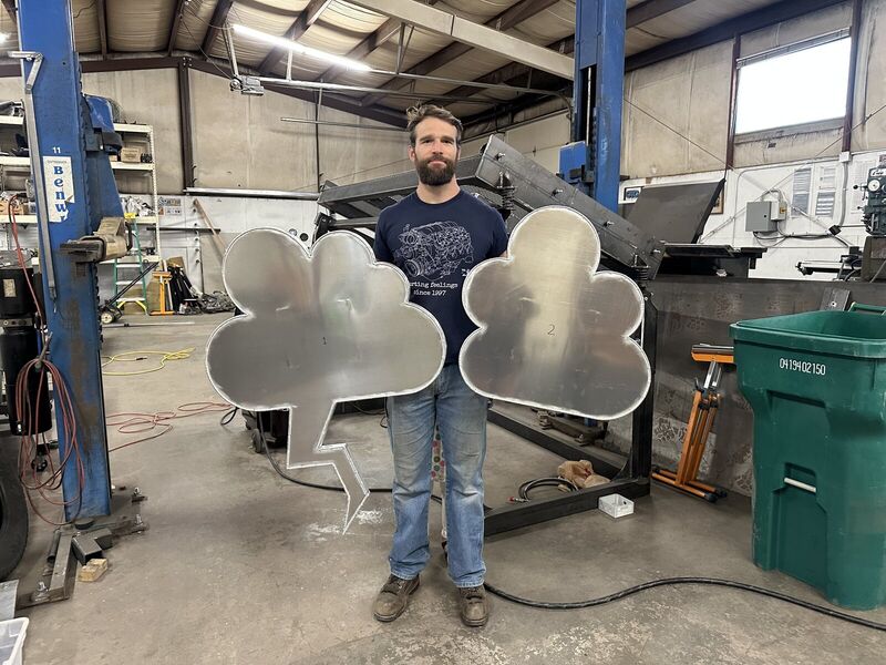
- The projectTruth or Consequences Contemporary, an art gallery in Southern NM, wanted to spice up the exterior of their building with some custom aluminum cloud signs.
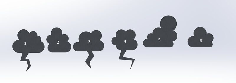
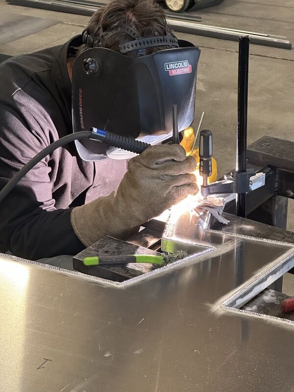
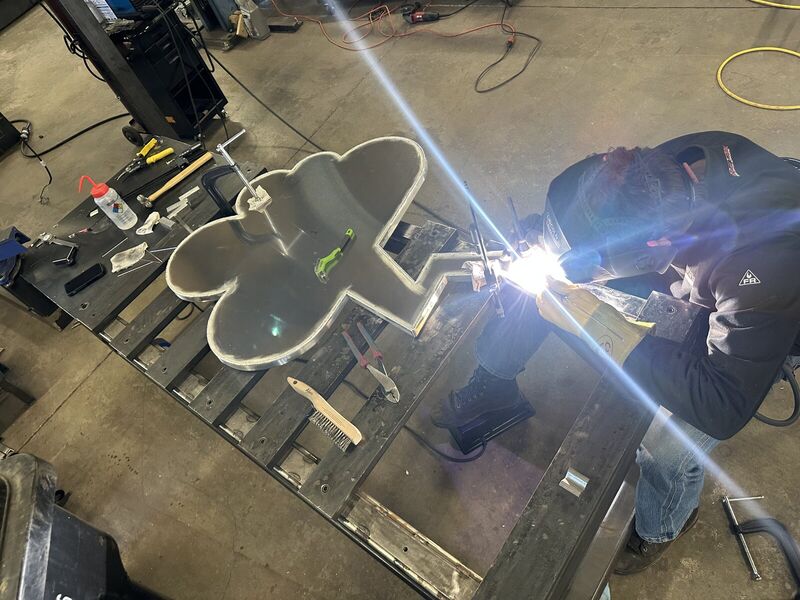
- The resultsThe artists provided the creative idea to make back-lit cloud signs out of aluminum. Mechanical Superiority provided the technical know-how to make it a reality. CAD designs were produced to make sure we were all satisfied with the aesthetic quality before going ahead with manufacturing. Mechanical Superiority then cut all of the required shapes on the in-house plasma table, designed and built custom sign mounts that would work with the building and installation plan, and welded it all together with great-looking TIG beads into a package that was pleasing to the eye. The cloud signs now act as an eye-catching feature that helps bring positive attention to the gallery, and brings unique aesthetic value to the community.
- Year2025
Aluminum tube frame with a canvas top
Ford 641 tractor frame
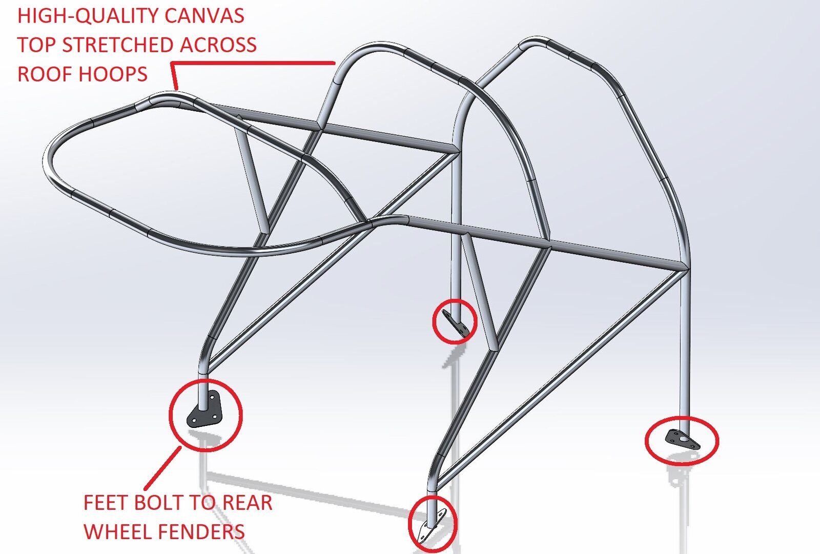
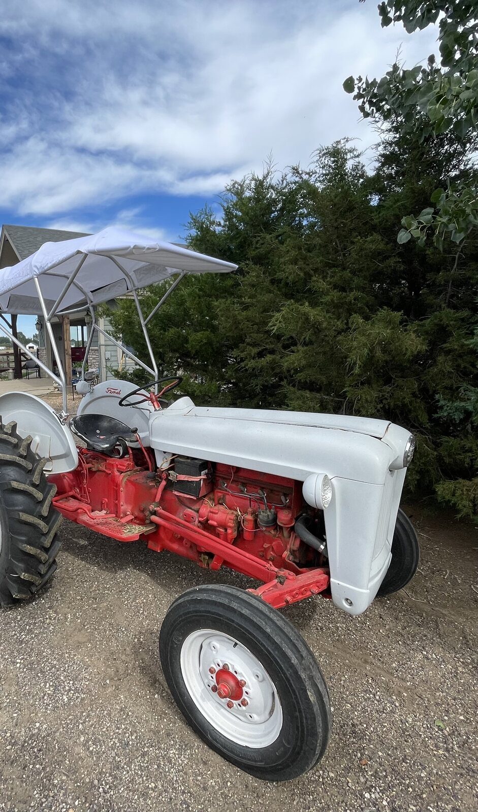
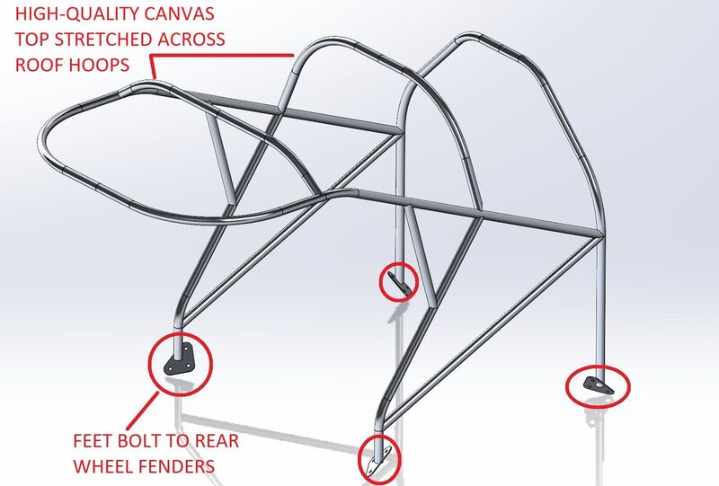
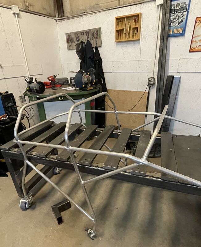
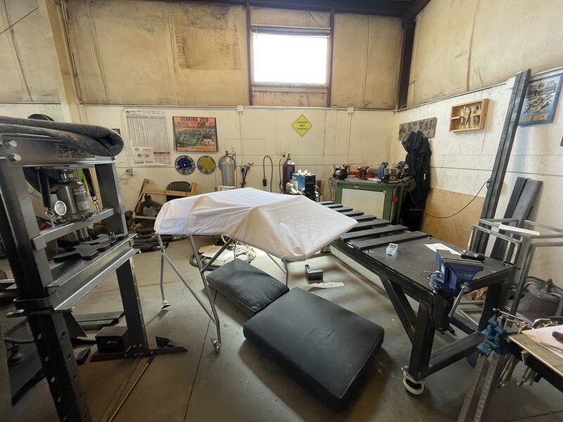
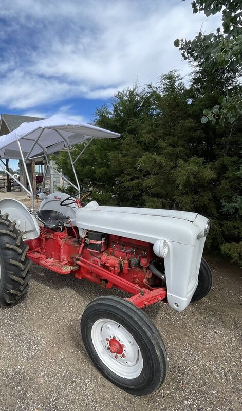
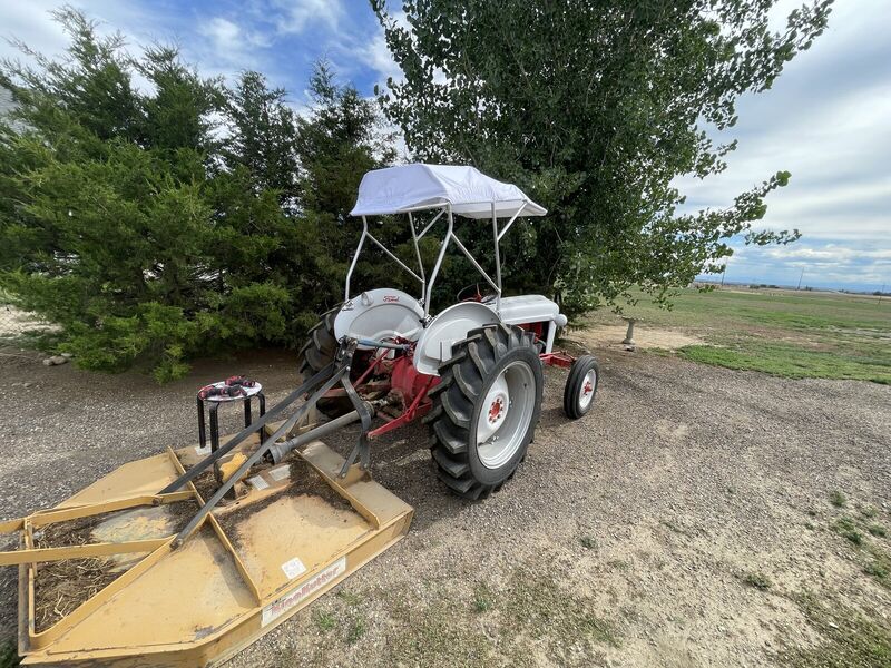
- The projectA local customer owned a beautifully maintained Ford 641 Tractor, and was looking for a shade structure to be added to improve the comfort level for mowing pastures on hot days. Initially, the customer wanted Mechanical Superiority to modify a boring off-the-shelf solution made from painted steel and plastic. With his creativity and advanced skills, Mark worked up a concept for a custom aluminum frame and matching canvas top. The customer was immediately sold on the idea based on the improved aesthetics and maintaining more of a classic look for the tractor. Plus, who else is ever going to have a super cool aluminum space frame shade structure on their old tractor?
- The resultsMechanical Superiority built and installed the one-off custom solution for the satisfied customer. To this day, everybody who sees the shade frame is immediately impressed by the quality of construction and the strength/durability of the structure. Classic looks, with space-age performance!
- Year2024
Industrial machinery, designed and built
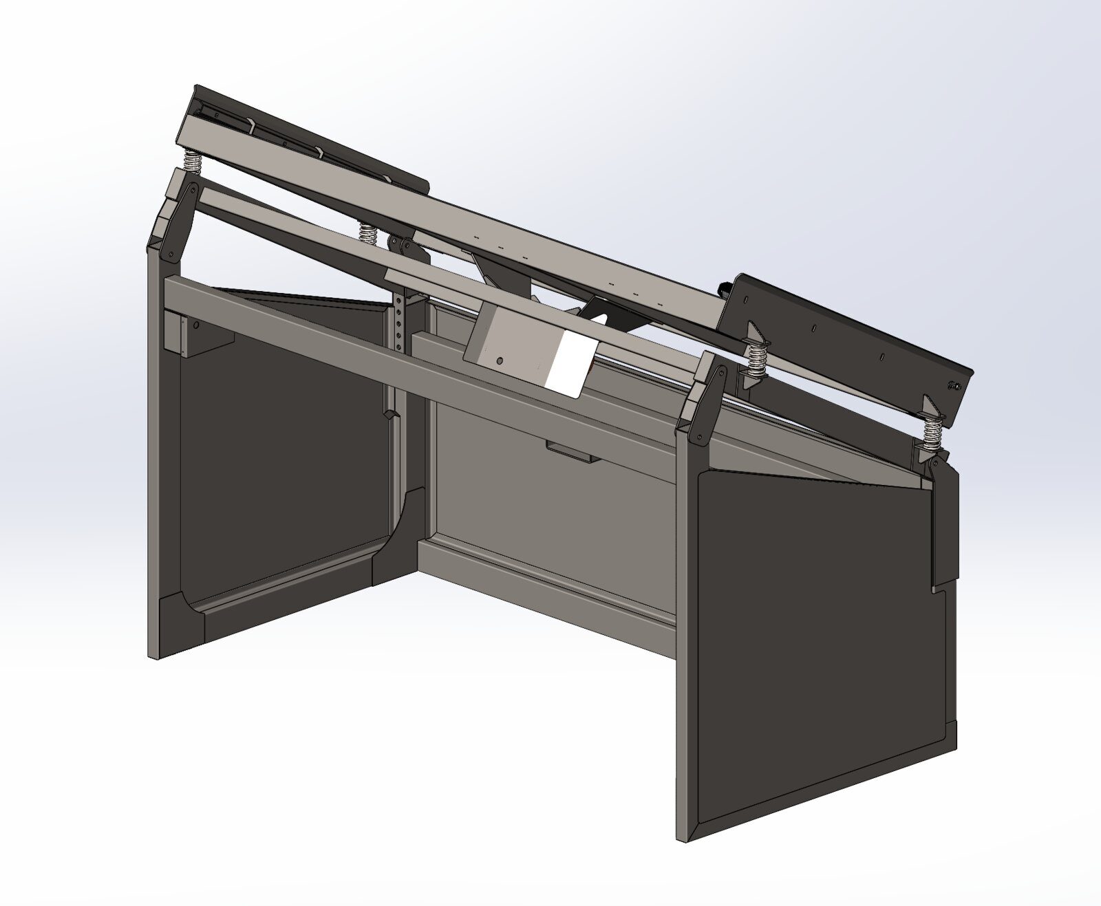
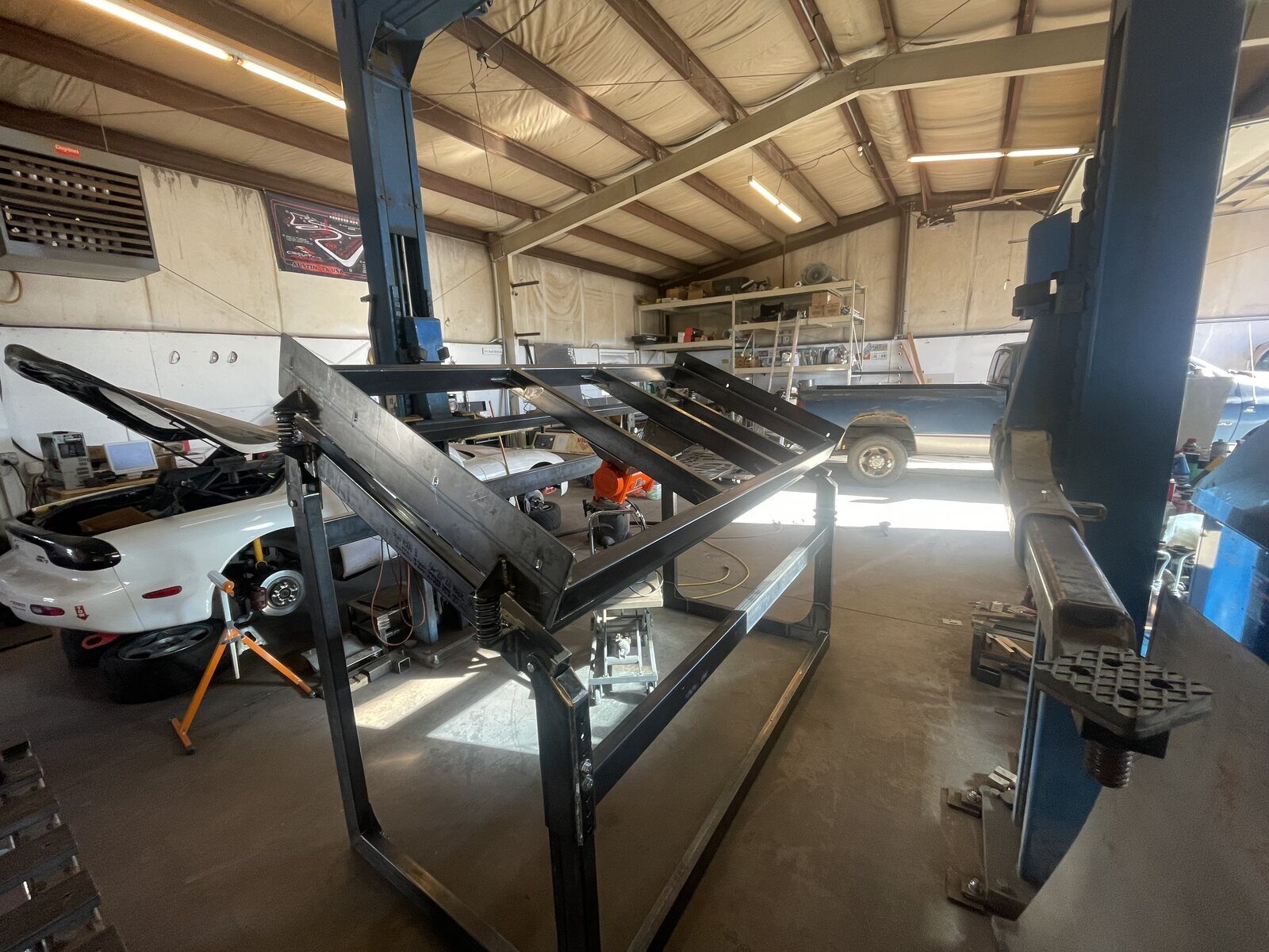
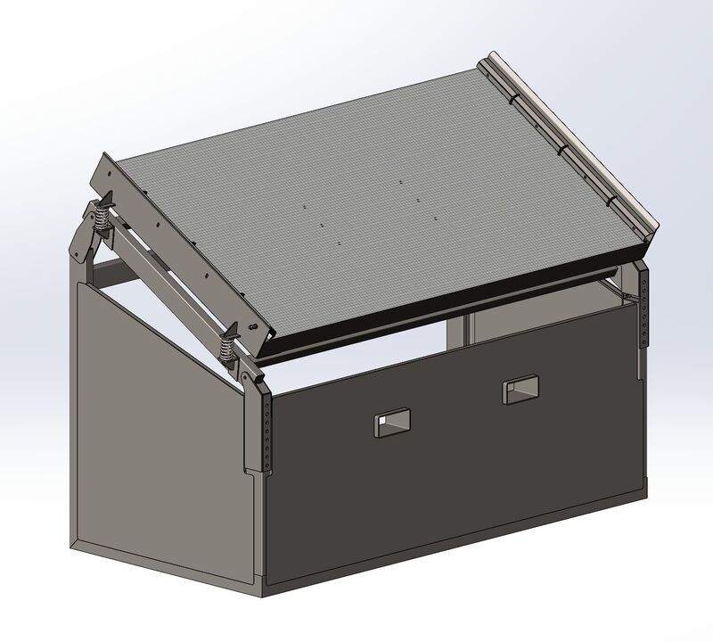
Topsoil screener
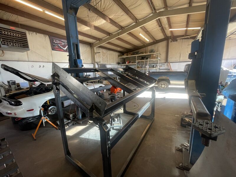
- The projectA customer was interested in developing a medium-duty topsoil screener for landscaping and agricultural use, but they didn't have the knowledge or experience to do it themselves.
- The resultsMechanical Superiority was able to employ some engineering math to properly select the components and shape the overall design. A full CAD design was then created for approval by the customer. A full set of shop drawings were then made for internal use, and a prototype of the machine was built for testing.
- Year2024
Small custom parts for performance
Racecar rear control arms
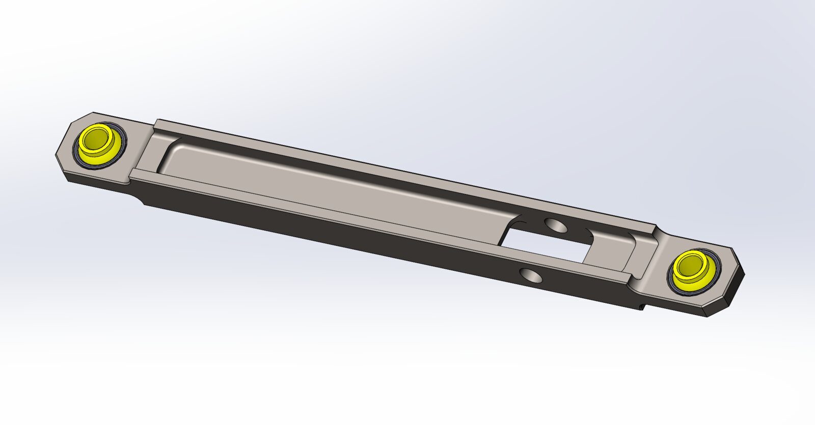
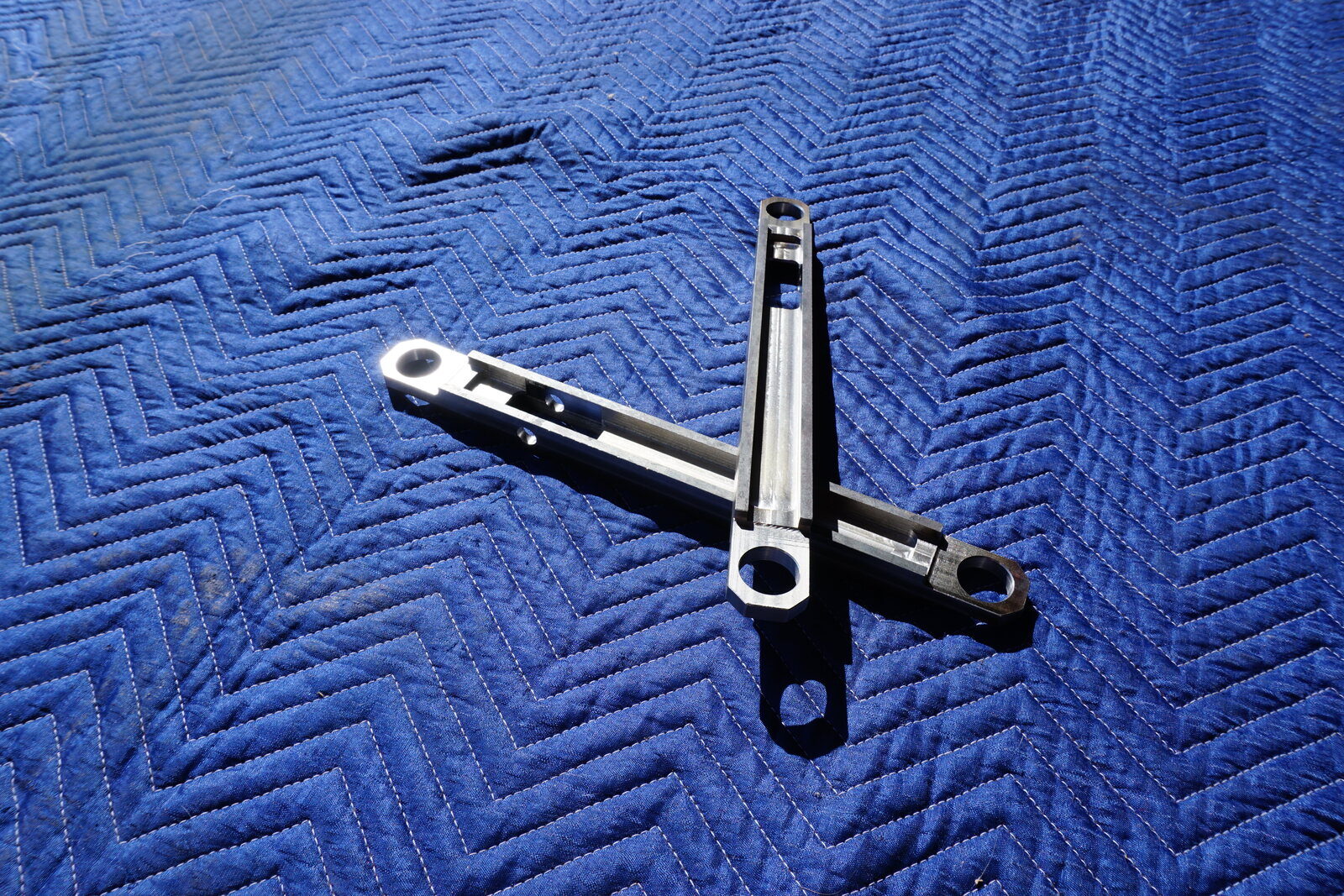
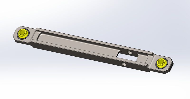
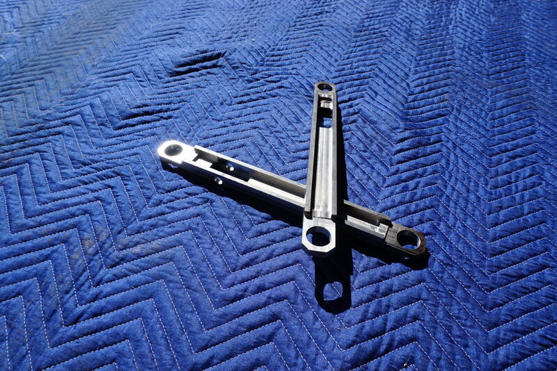
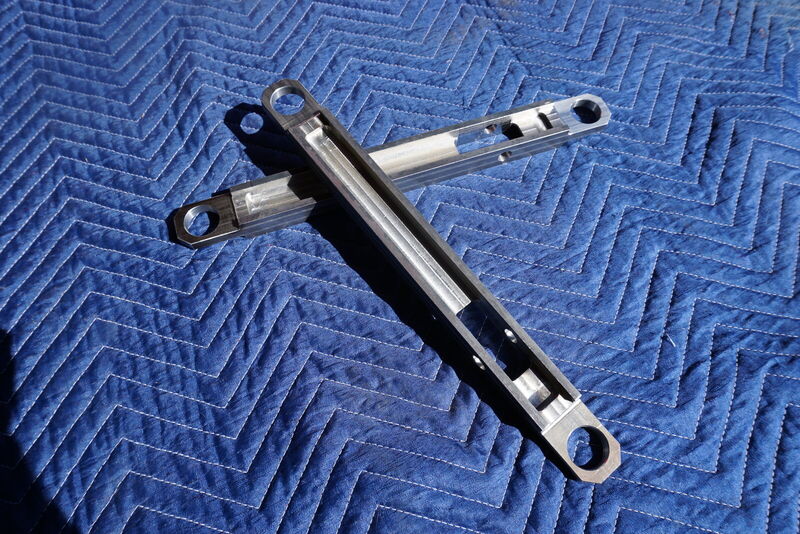
- The projectMy very own LS1-swapped RX7 is a great track platform; with a lightweight chassis and excellent suspension setup for road racing. Once my driving skills improved past a certain point, I started to notice that the rear end of the car felt excessively "twitchy" in mid-corner handling when adding throttle. By using some simple engineering analysis and employing my own deep intuitive understanding of the chassis as a system, I was able to narrow the problem down to probable excessive bushing compliance on the rear Lower Control Arms (LCA's).
- The resultsI designed and manufactured my own rear control arms with solid spherical joints to eliminate the rear toe-compliance. Once the new LCA's were installed, I headed to the track to test them out. What a world of difference! The rear end now feels solidly planted, and I can drive through corners with absolute confidence. Although this type of design is likely too extreme for a road car, it is just what was needed for a full race application. And don't they look beautiful?
- Year2022
Tell me what you're trying to build
A drawing, a model, or even just a napkin sketch: I can help you to refine your idea and make it a reality. If you're not sure about the finer particulars (like tolerances or materials selection), that's totally fine. With my experience, we can help nail the details so that the design turns out right the first time.
mechanicalsuperiority@gmail.com 970-587-3271 What to send for a quote